top of page

Construction
The spindles have been machined from 1-inch aluminum round stock. The diameters were all machined using a lathe with a live center. The 5/8-11 machine threads were then cut using a a standard die. The end of the spindle that will be coped to the spindle tube was then radiused using a 1” end mill.
The spindle tubes were cut to length in the machine shop from 1” aluminum round tube. Cut to length via a band saw.
Mounting the ball-joint will required manufacturing mounting plates. Four mounting plates were machined from ¼” aluminum plate via the use of a mill.
The steering arms were cut to length from ¼” aluminum via the band saw. Tie rod end holes were then drilled in the arms for variability of steering.

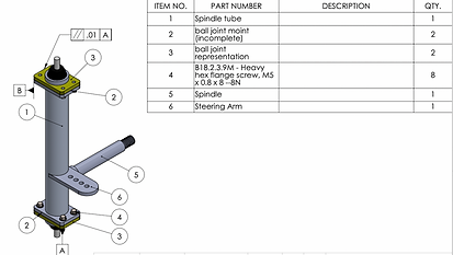
Spindle Assembly Drawing
Full Report
Spindle Assembly Completed Components
Turning the spindle
Milling Ball joint Mounts
Welding the Spindles (Courtesy of Under Pressure Racing)


Completed Spindles

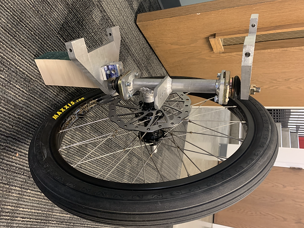
Right Side Suspenstion (Off Vehicle)
The new upper control arms needed a new frame piece welded in place in order to mount onto the chassis. The Ellensburg Washington local business "Dave's Exhaust" donated professional welding services and expertise to the project. Dave is a welding expert who has experience building drag race cars. His expertise was invaluable during this process. He helped to ensure proper geometry was kept while mounting the new suspension.
Mounting
Welding of the frame mounts
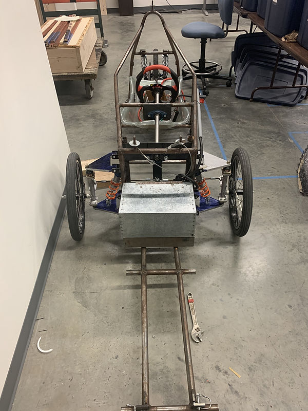
Initial Mock-up

The new spindle assembly interferes with the shock mount assebly upon turning the wheel. This was expected and several mounting options were considered to remedy this.
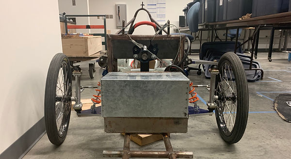
However, it was decided the best way to proceed would be to manufacture 4 new control arms, adding 2 inches of width to the control arms.
Construction Complete:


bottom of page